I Built a Keyboard (Part 2)
Previously
In the last post, I talked about my ability to solder, my progression of keyboards, and how I rolled the dice on a pre-made Sofle RGB from AliExpress.
Keyboard (Number Two)
Procurement
With the first keyboard in a box and ready to go to China, I figured I’d give this whole thing a crack the conventional way. Previously, I explained that because the keyboard is open source, it’s possible to have the pcb fabricated and to source the parts yourself. I wanted to speed that process up and found that there are websites dedicated towards making the process easier but, again, to the extent that you might need a spreadsheet to determine if you have all of the items on the Bill of Materials. What I mean by that is that some vendors would have the kit but not a microcontroller. Some would include the microcontroller but not the rotary encoders. Also, these things would be for sale on their website but maybe not.
What I ended up going with was a kit from diykeyboards.com. Again, they were missing microcontrollers and rotary encoders from the kit but they did have it on their site and it was not sold out. Shipping was relatively fast with it being in Pennsylvania.
Actual Building
Following a combination of the official but also better instructions from another vendor. Between the combination of these, I was on my way.
First Couple Steps
I needed to flash the microcontrollers with the firmware from the Beekeeb site. Next was the step of soldering the SMD diodes on to the board. SMD are usually difficult but this was no problem as the diodes were not super small. I had to bridge some pads so that the pcb, which is double sided and ambidexterous, knows which side to use. Remember how I fried my previous microcontroller? I wanted to avoid that by adding sockets to the board for the microcontroller and pins for the microcontroller. Unfortunately, the pins that the site included with the microcontroller were too large for the socket holes and I had to improvise by using 24AWG wire and soldering them in, one by one. I had to do this later with the OLED display as well.
At this point, I could test it by plugging it in and touching the contact point with tweezers. Luckily, everything worked and I could continue on. The Kailh switch sockets were next and that went seamlessly too. TRS jack, reset button, rotary encoder, OLED display? Check, check, check, check. I had to jumper some pads which determine which lighting configuration I’ll be using. No problem there.
LEDs from Hell
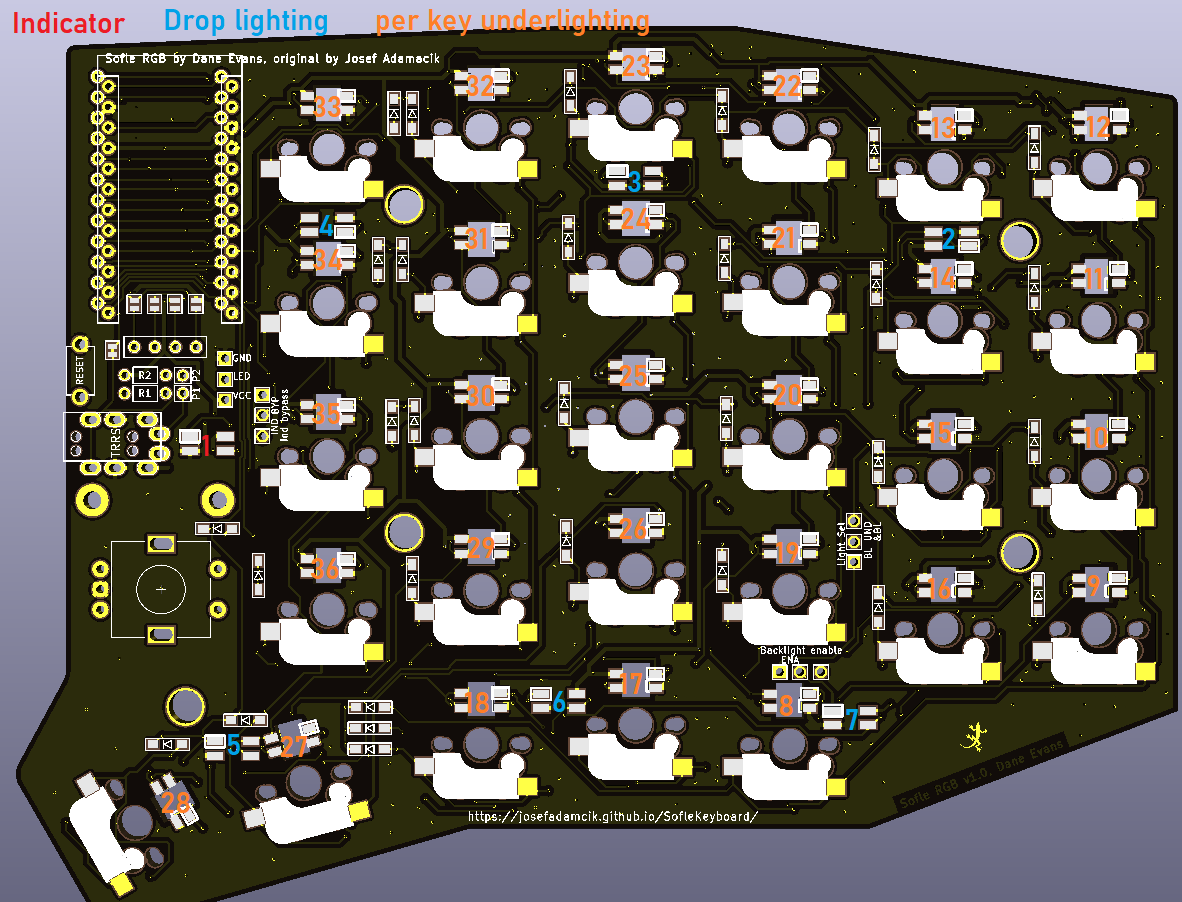
Now come the LEDs. The keyboard has 72 LEDs and the kit included 80 of them. For the status indicator and backlights, these are surface mounted which means that you need to douse the board with flux and pray that the LED is flat enough and that the solder wicked up from the pad, which you can see, to the underside of the LED, which you can’t. Oh, and because each LED has a little bit of logic in it, you can’t overheat it otherwise it will die. This was challenging but I got those first 7 LEDs on with little to no problem.
In order to do the per-light LEDs, I needed to place it in a hole in the PCB in the correct orientation.
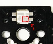
The tolerance here was so tight but you had to gently nestle that LED in just right and in the middle. Then solder it with absolutely no gaps. So, I followed the instructions of soldering the LED and testing but it wouldn’t work and was super frustated. Did I have an air gap in the solder? Did I overheat the LED? Was the LED faulty? I would remove it and toss the LED and try again with no luck.
It is here I’d like to stop and point something out. Take a moment to look at this image:
Does anything strike you about this? This is from the official documentation and not the much more, up to this point, comprehensive Beekeeb documentation. It turns out that the LEDs (SK6812) are commonly used in those strips of LED lights and each one is addressable but this means that they need to be in a chain and that’s how the circuit board is configured but going off of the Beekeeb documentation, this is not clear.
Once I figured that out, It made more sense and made it easier to debug as I could trace down the LED that was prone to any of the issues I just mentioned. By the point I figured this out, though, it was too late and I had blown through my extra LEDs. I wouldn’t have enough to finish the entire thing.
Assembly
The rest went super smooth. Sockets went in without ripping pads off, unlike the first keyboard. I didn’t have a case yet but I was able to test things out without much worry.
Software
There is an open-source keyboard software package called QMK that I mentioned in the first part. The gist of it is that the keyboard makers add their keyboard to this repo and it is up to the user to clone this repo and compile it using the qmk tool. Configuration is done by editing a configuration locally and then recompiling.
This is done with the command qmk compile -kb sofle/rev1
Luckily, people have mercifully written software to go on top of QMK that enables altering the keyboard on the fly. The first keyboard used VIAL but when I went to try to install that, there was much thrashing about and nothing seemed to work.
It turns out that there is another GUI for this type of thing called VIA but it was mysterious as to how to get my keyboard to be recognized by VIA. The QMK firmware from the BeeKeeb tutorial was recognized but the QMK firmware I compiled myself wasn’t. There must have been something going on.
According to the docs, it was the steps of adding VIA_ENABLE = yes to the rules.mk file and then compiling. Then, when compiling the QMK firmware, I need to change the keymap to via with qmk compile -kb sofle/rev1 -km via.
After I did this, I was able to see the keyboard in Via in order change the keys & lighting and test the keys.
What the Heck
By this point, I had gotten another batch of LEDs from China and soldered them all in. It went smoothly but the last two on the right side would not work. I took them out, replace them, tested with the multimeter. I went to go reflash the firmware when I notice that when I plugged in the right side (in order to flash it), those LEDs which weren’t working were and the last two on the left side wouldn’t work.
It turns out that the QMK keymap for VIA is incorrect and has a constant of 70 LEDs when it should have 72. Luckily, someone has fixed this.
Still, the LEDs will glitch from time to time and I already broke one which I tapped a little to hard to see if there was a cold solder joint
Nice Cozy Home
The last component was a case for it which I found on Thingiverse. I ordered the hardware from AliExpress and they came with the LEDs. I had to find some thread protectors at Home Depot to act as rubber feet for the adjustable hex screws on the bottom of the legs.
## All Done?

I’m pretty pleased with it! Sometimes the LED glitch out and, when the computer is asleep, I’ll come back to the keyboard jamming on the “V” and Enter key but I just unplug it and it’s fine when plugged back in. Maybe it’ll be fixed in the future.
It was a fun project that maddening with the LEDs but pretty rewarding overall.